Turnout controller Example
Under Construction
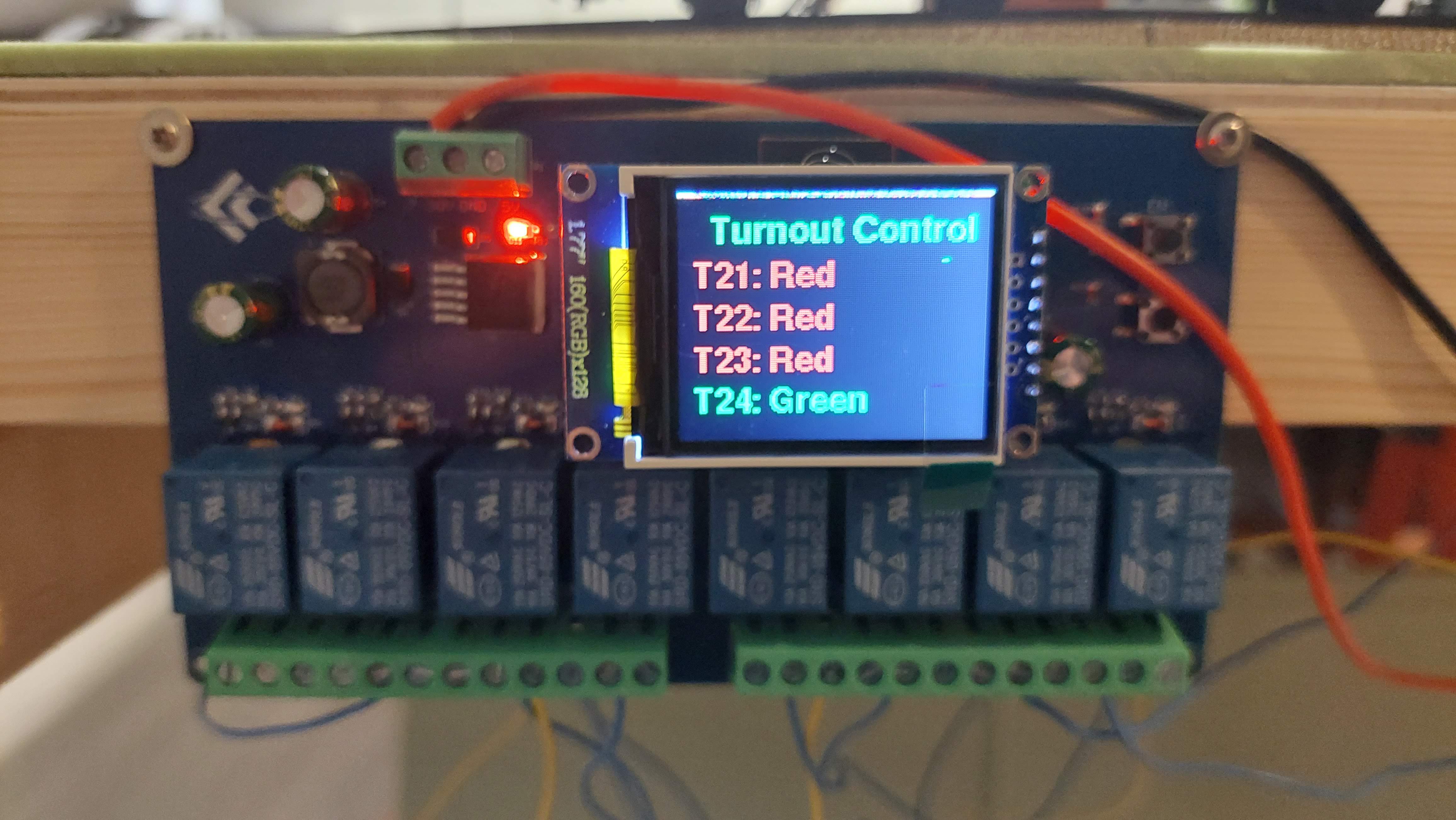
This is a example of a hardware implementation for controlling 4 solenoid turnous by a 8 channel ESP32 Relay board
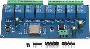
Documentation of the relayboard by Werner Rothschopf
Modifications on the Board
To supply the board and turnouts with a single 12V DC adapter, make the folowing modifications. You need only supply the board through the DC7-30V and GND connections(DC5V can be left open)
Wire 12 Volts
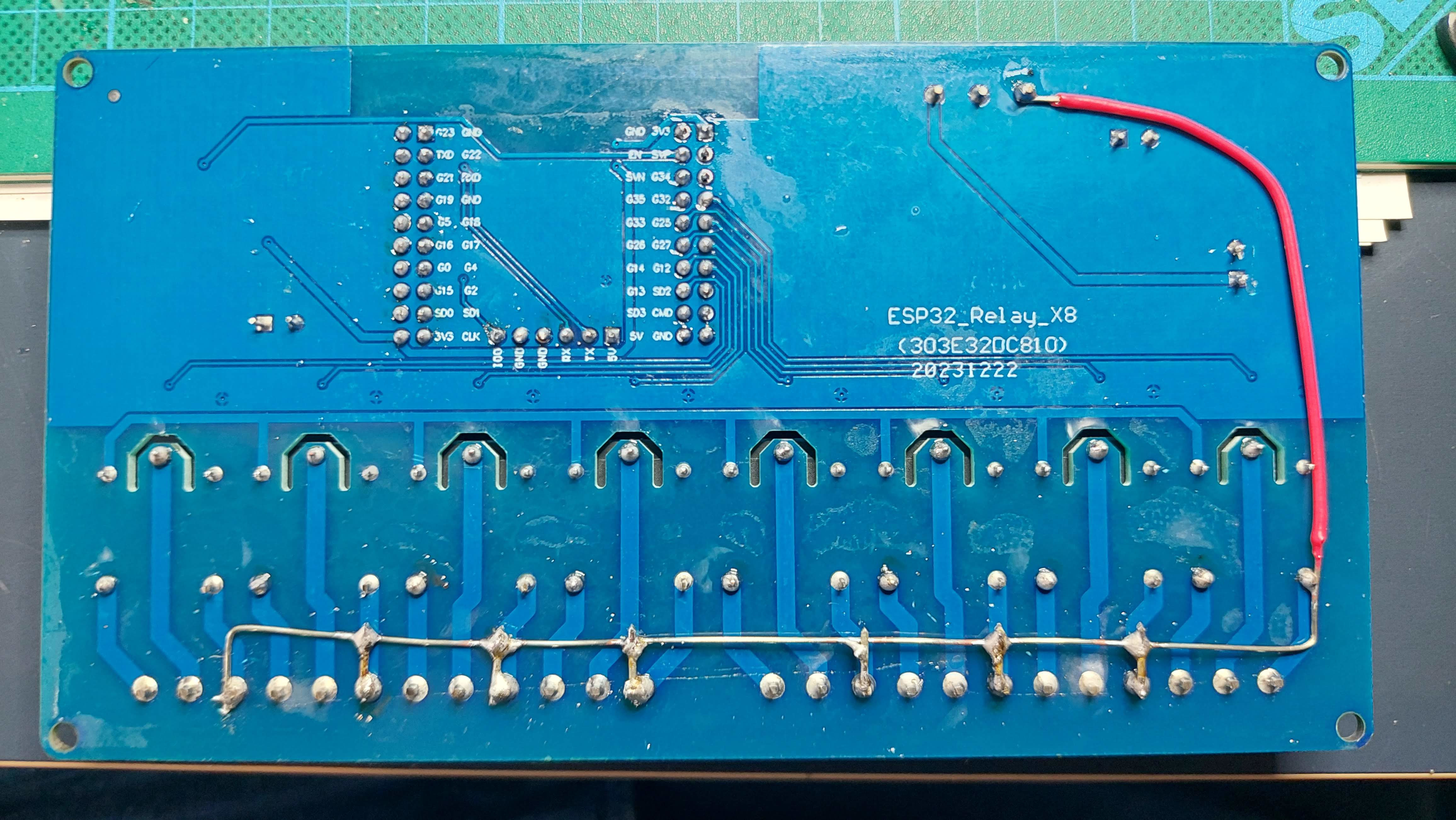
Wire diodes (Optional, to prevent burning-in relay contacts)
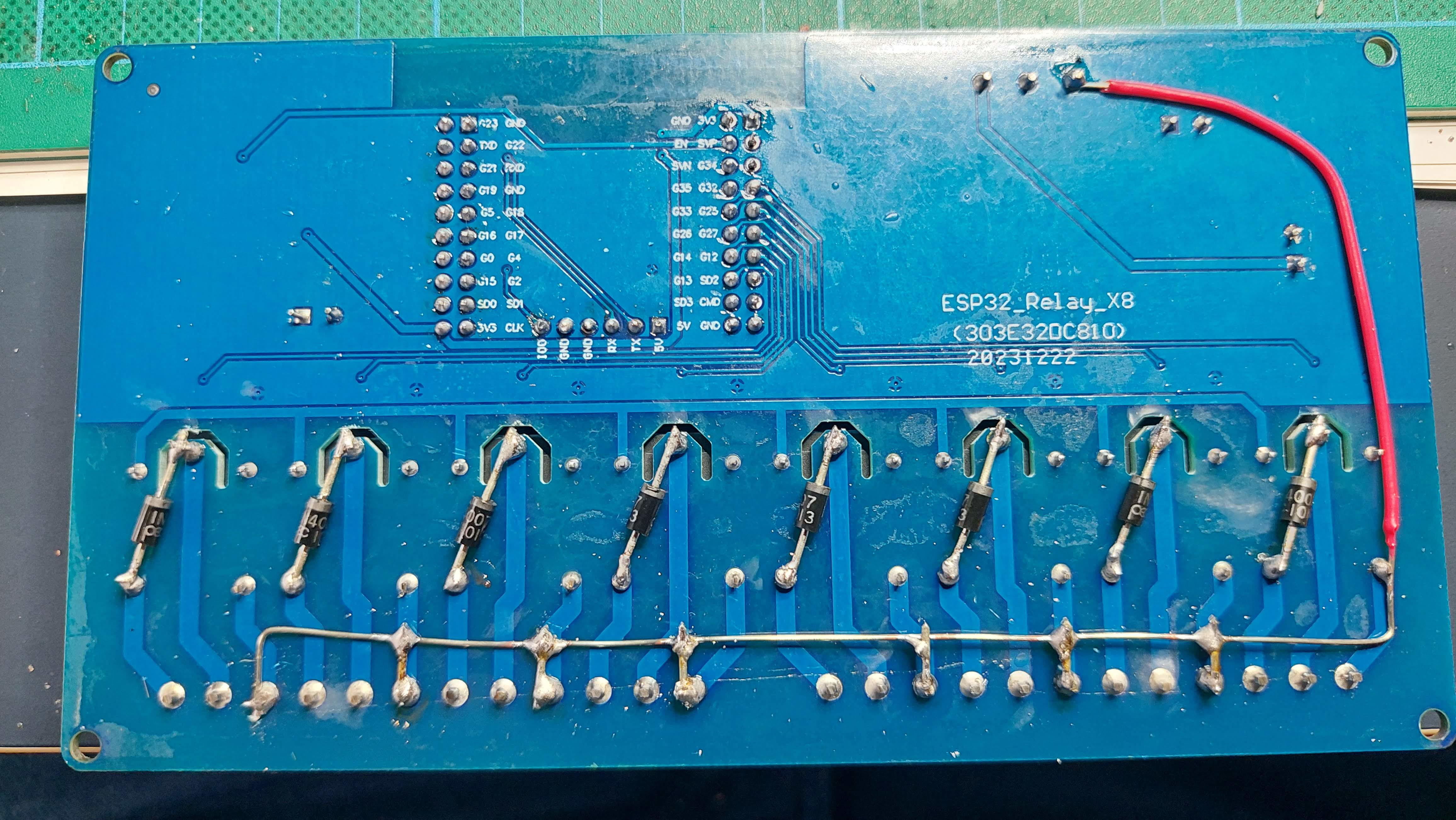
Wire GND
Connections of the turnouts
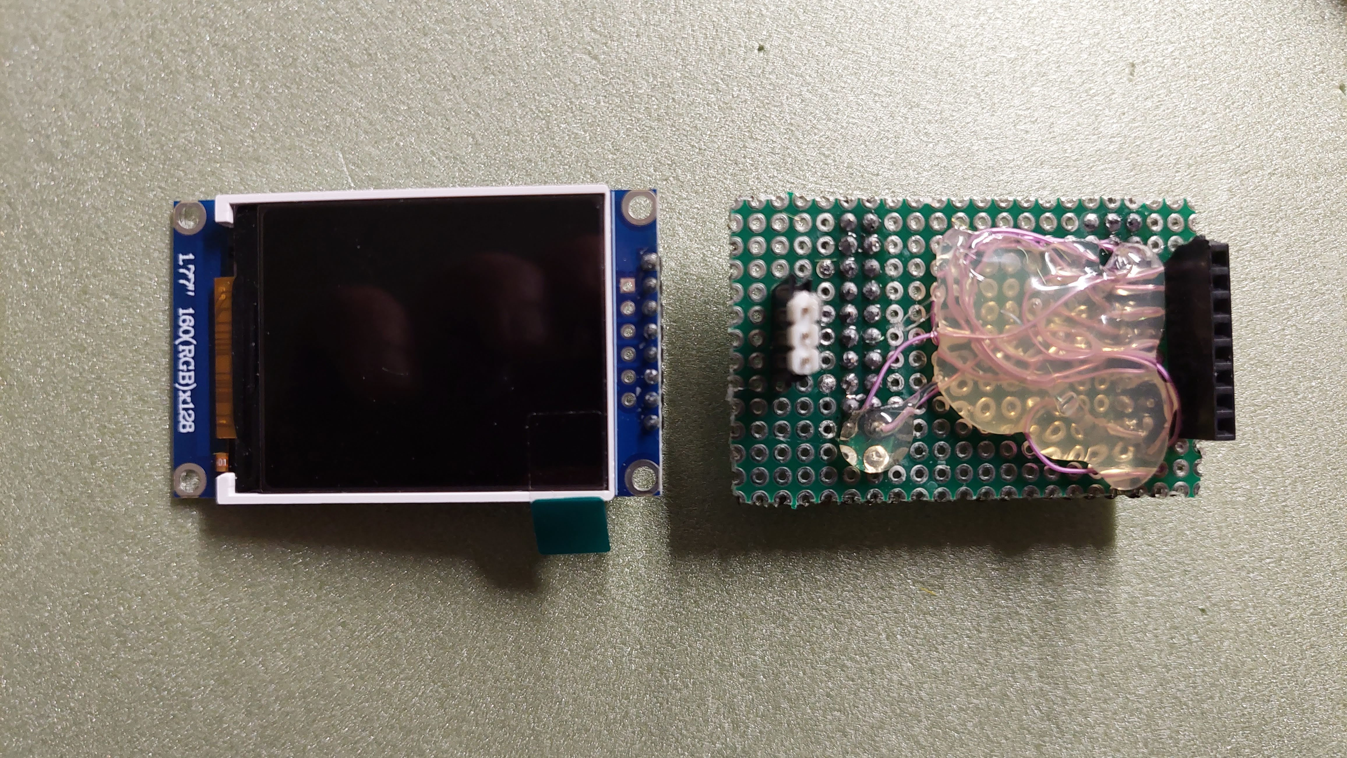
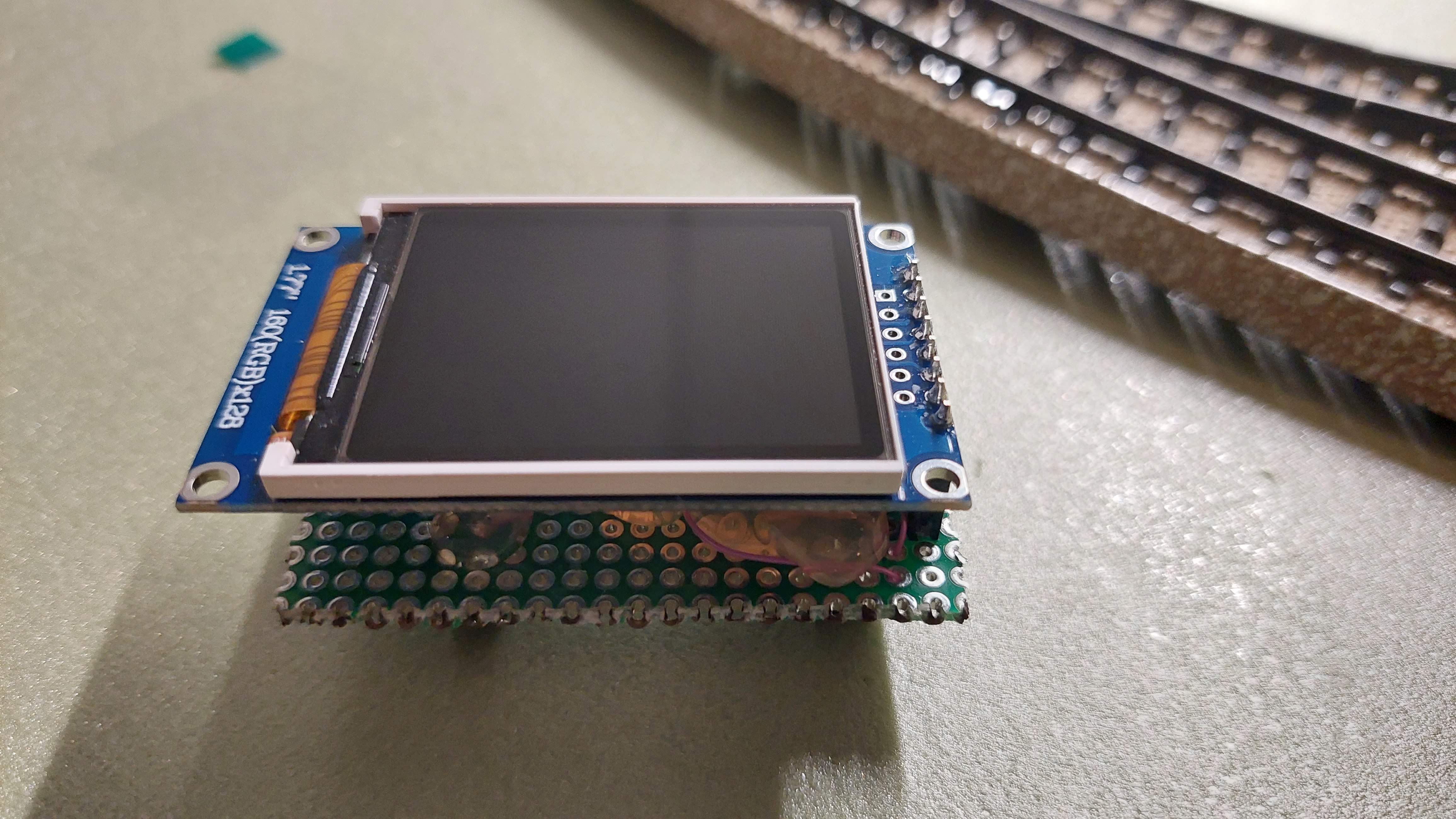
Extend the board with a (status)display
Optionaly extend the controller with a display.
Adaptor for the display
Example of configuration
The files turnout_config_a.json and turnout_config_b.json in the config directory of this repository gives a good example of configuring the board.
Note: Every controller should have an unique node name defined in de configuratuin file)
Programming instructions(Note: Select project ros2_turnout_controller)